The NHRC-2 is an inexpensive repeater controller with real stored speech and DTMF remote control. It is available assembled and tested, or as a partial kit. The partial kit contains the printed circuit board, a programmed PIC microcontroller, a MT8870 DTMF decoder, and a complete manual on CD-ROM. The manual contains ordering information for all the remaining parts needed to build the controller.
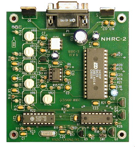
NHRC is pleased to present the NHRC-2 revision D Printed Circuit board! This new layout features a smaller footprint, improved power routing to the ISD chip for less noise, as well as silkscreened parts placement on the component side to simplify assembly.
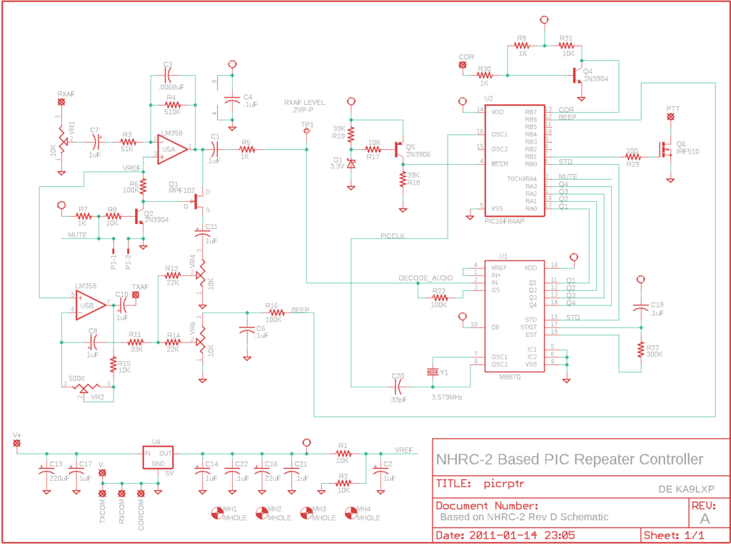
Schemat:
Features:
- 4 stored voice messages (initial ID, normal ID, timeout, and tail or courtesy beep message)
- „Intelligent” ID algorithm.
- 3 Operating Modes:
- Duplex Repeater Controller
- Simplex Repeater Controller
- Link Controller
- Touch-Tone remote control and programming.
- Hang timer, ID timer, Timeout timer.
- Extremely low power consumption.
Pliki dokumentacji:
NHRCSCH.PDF- Project Schematic
NHRCART.PDF- Copper Artwork (mirrored)
NHRCGND.PDF- Copper Groundplane (mirrored)
NHRCPART.PDF- Parts Placement Diagram
NHRCLIST.PDF- Project Bill of Materials
README.TXT- This file.
Pliki programu EAGLE:
PICRPTR.SCH- Schematic File
PICRPTR.BRD- PCB File
PICRPTR2.CAM- CAM Job
PICRPTR.ERC- Error List
PICRPTR.LST- Parts List
NHRCBOM.XLS- Materials Spreadsheet
PICRPT_1.PS- Postscript PCB Art – 1 board
NHRC08.PS- Postscript PCB Art – 8 boards
Pliki z oprogramowaniem:
NHRC-2 Repeater Controller Quick Reference
| Pin | Use |
|---|---|
| 1 | Ground |
| 2 | +13.8 Volts |
| 3 | PTT (active low) |
| 4 | TX Audio |
| 5 | RX Audio |
| 6 | CAS + |
| 7 | CAS – |
| 8 | Ground/TX Audio Return |
| 9 | Ground/RX Audio Return |
| Bit | Hex Weight | Feature |
|---|---|---|
| 0 | 01 | ISD Absent |
| 1 | 02 | Simplex repeater mode |
| 2 | 04 | n/a |
| 3 | 08 | n/a |
| 4 | 10 | suppress courtesy tone |
| 5 | 20 | suppress DTMF muting |
| 6 | 40 | use tail message for courtesy tone |
| 7 | 80 | n/a |
| Command | Description |
|---|---|
| 400x | 0 <= x <= 3, play CW message x |
| 401x | 0 <= x <= 3, play voice message x |
| 410x | 0 <= x <= 3, record voice message x |
| Message Number | Stored Voice | CW |
|---|---|---|
| 0 | Initial ID | ID message |
| 1 | Normal ID message | timeout message („TO”) |
| 2 | Time-out Message | confirm message („OK”) |
| 3 | Tail Message | invalid message („NG”) |
| Address | Default Data | Comment |
|---|---|---|
| 00 | 01 | enable flag |
| 01 | 00 | configuration flags |
| 02 | 32 | hang timer preset, in tenths |
| 03 | 1e | time-out timer preset, in seconds |
| 04 | 36 | id timer preset, in 10 seconds |
| 05 | 00 | tail message counter |
| 06 | 0f | ’O’ OK Message |
| 07 | 0d | ’K’ |
| 08 | ff | EOM |
| 09 | 05 | ’N’ NG Message |
| 0a | 0b | ’G’ |
| 0b | ff | EOM |
| 0c | 03 | ’T’ TO Message |
| 0d | 0f | ’O’ |
| 0e | ff | EOM |
| 0f | 09 | ’D’ CW ID starts here |
| 10 | 02 | ’E’ |
| 11 | 00 | space |
| 12 | 05 | ’N’ |
| 13 | 3e | ’1′ |
| 14 | 0d | ’K’ |
| 15 | 09 | ’D’ |
| 16 | 0f | ’O’ |
| 17 | 29 | ’/’ |
| 18 | 0a | ’R’ |
| 19 | ff | EOM |
| 1a | 00 | can fit 6 letter ID…. |
| 1b-37 | not used | |
| 38 | n/a | isd message 0 length, in tenths |
| 39 | n/a | isd message 1 length, in tenths |
| 3a | n/a | isd message 2 length, in tenths |
| 3b | n/a | isd message 3 length, in tenths |
| 3c | n/a | passcode digit 1 |
| 3d | n/a | passcode digit 2 |
| 3e | n/a | passcode digit 3 |
| 3f | n/a | passcode digit 4 |
| Character | Morse Code | Binary Encoding | Hex Encoding |
|---|---|---|---|
| sk | …-.- | 01101000 | 68 |
| ar | .-.-. | 00101010 | 2a |
| bt | -…- | 00110001 | 31 |
| / | -..-. | 00101001 | 29 |
| 0 | —– | 00111111 | 3f |
| 1 | .—- | 00111110 | 3e |
| 2 | ..— | 00111100 | 3c |
| 3 | …– | 00111000 | 38 |
| 4 | ….- | 00110000 | 30 |
| 5 | ….. | 00100000 | 20 |
| 6 | -…. | 00100001 | 21 |
| 7 | –… | 00100011 | 23 |
| 8 | —.. | 00100111 | 27 |
| 9 | —-. | 00101111 | 2f |
| a | .- | 00000110 | 06 |
| b | -… | 00010001 | 11 |
| c | -.-. | 00010101 | 15 |
| d | -.. | 00001001 | 09 |
| e | . | 00000010 | 02 |
| f | ..-. | 00010100 | 14 |
| g | –. | 00001011 | 0b |
| h | …. | 00010000 | 10 |
| i | .. | 00000100 | 04 |
| j | .— | 00011110 | 1e |
| k | -.- | 00001101 | 0d |
| l | .-.. | 00010010 | 12 |
| m | — | 00000111 | 07 |
| n | -. | 00000101 | 05 |
| o | — | 00001111 | 0f |
| p | .–. | 00010110 | 16 |
| q | –.- | 00011011 | 1b |
| r | .-. | 00001010 | 0a |
| s | … | 00001000 | 08 |
| t | – | 00000011 | 03 |
| u | ..- | 00001100 | 0c |
| v | …- | 00011000 | 18 |
| w | .– | 00001110 | 0e |
| x | -..- | 00011001 | 19 |
| y | -.– | 00011101 | 1d |
| z | –.. | 00010011 | 13 |
| space | 00000000 | 00 | |
| EOM | 11111111 | ff |
Repeater Controller Mode
The controller has an ID timer which can trigger 1 of 2 stored voice IDs, or the CW ID. The IDs are controlled by a user-programmable ID timer, which can be set from 10 seconds to 2550 seconds. Normally this will be set to a value less than 600 seconds (the FCC-mandated 10 minute ID time.) The controller will play the „initial ID” if it has been quiet for one entire ID cycle (that is, the time specified by the ID timer has elapsed since the repeater’s last transmission.) The initial ID might contain a message such as „Welcome to N1KDO repeater.” The „normal ID” will play after the ID timer expires. The normal ID would typically contain a short ID message like „N1KDO repeater.” The controller tries to be „polite” about when it IDs; if a user unkeys and the ID timer has 60 seconds or less remaining before playing an ID message, the controller will ID immediately in an attempt to keep the ID from playing on top of another user. If a user keys up while a stored voice ID is playing, the controller will cancel the stored voice ID and play the CW id. Also, if a user keys the repeater, and the controller plays the initial ID, the controller will not play the normal ID after the ID timer expires unless the repeater is keyed again. This prevents unnecessary IDing by the repeater.
The controller provides a hang timer and a courtesy tone. The hang timer keeps the repeater’s transmitter on for a short time after a user unkeys. This reduces cycling of the repeater transmitter and can eliminate some of the squelch crashes on the user’s that are caused by the repeater’s transmitted signal dropping. The hang timer can be programmed for a delay from .1 second to 25.5 seconds. The courtesy tone is a short beep that sounds after a user’s transmission has ended and the time-out timer has been reset. (Note that the time-out timer is reset before the courtesy tone is heard.)
The controller has a user-programmable time-out timer, which can be set from 1 second to 255 seconds. The time-out timer prevents damage to the repeater’s transmitter in the event of a user sitting down on his microphone before starting a long ride, or the repeater’s receiver becoming unsquelched for some reason. The time-out message plays when the time-out timer expires and when the time-out condition ends, so people listening to the repeater are aware of the time-out condition as soon as it happens, and the offending operator knows that he timed out the repeater when the time-out condition ends.
A tail message can be selected to play after a programmed number of expirations of the hang timer. This message can be used to advertise a net or club meeting, to warn of inclement weather, etc.
Link Controller Mode
The controller can be used to control link radios for remote receivers or split-site repeaters. In link controller mode, the controller does not use any stored voice messages; it only will ID in CW. This allows the controller to be built without the ISD1420 and associated support circuitry, lowering the cost for link support. In most link controller modes, the hang time would be set to zero.
Simplex Repeater Controller Mode
The controller can also be used to run a „simplex repeater”. A simplex repeater records up to twenty seconds of audio from the receiver, then plays the recorded audio back out the transmitter. In this mode, the controller will ID in CW when the ID timer expires.
Power Consumption
The controller is ideal for remote solar and battery powered applications. In standby mode, less then 10 mA of current is drawn. Worst case current consumption occurs when messages are recorded into the ISD1420 chip, and that is under 30 mA. Normal repeater operation requires less than 20 mA.
Circuit Description
The controller consists of a Microchip PIC 16C84 microcontroller IC, a Teltone M8870 DTMF decoder IC, a ISD 1420 voice record/playback IC, and a CMOS operational amplifier IC.
The heart of the controller is the Microchip PIC 16C84 microcontroller (U1). The 16C84 features 13 I/O leads, 1024 word of program storage, 36 bytes of RAM, and 64 bytes of EEPROM (non-volatile memory) in a 18-pin DIP. It is a RISC-like (reduced instruction set computer) Harvard architecture computer (it has separate program and data stores), and is extremely fast. In the repeater controller application, the PIC 16C84 executes over 800,000 instructions per second (.8 MIP!). The 16C84 provides all the timers, CW generation, DTMF validation, and other digital I/O requirements of the controller. The 16C84 uses the 3.58 MHz clock generated by the DTMF decoder.
DTMF tones are decoded by the Teltone M8870 (U3). The M8870 decodes DTMF by filtering the received audio signal into its high and low components, and counting the frequency of each component. Because it uses this approach, it is much less likely to detect voice as a DTMF digit and generate a false decode. When a valid digit is decoded, the M8870 raises the StD (delayed steering) lead, which informs the 16C84 microcontroller that a valid touch tone has been received.
Speech messages are stored in the ISD 1420 (U2). This device stores speech by recording analog levels into flash EEPROM cells, rather than storing digital values. The ISD1420 can address up to 160 different messages of 125 ms each, but in the controller application, we chose to implement 4 messages of approximately 5 seconds each. The device’s address lines are configured to allow messages to start at the 0-, 5-, 10-, and 15-second addresses. Device address, playback and record are controlled by the PIC 16C84.
Audio processing uses an optional de-emphasis circuit that provides a -6dB/octave slope to de-emphasize receiver audio, which allows the controller to be fed with the receiver’s discriminator output, rather than an already deemphasized source of audio, such as a line or speaker output. A FET(Q1) mutes the audio when the receiver is squelched or DTMF tones are present. A simple audio mixer combines receiver audio, ISD 1420 audio, and beep tone audio into the transmitter input.
Software Description
The controller’s PIC 16C84 microcontroller chip would do absolutely nothing without software. The controller’s software handles all DTMF validation, beep generation, timing, CW sending and control required by the ISD1420 and the repeater itself. The source code is nearly 1500 lines of assembler, and uses 85% of the available program storage on the PIC. The program uses 32 of 36 bytes of RAM on the PIC, and more than half of the EEPROM. The operation of the software can be loosely described as a polled loop, with interrupt-based timing. The source code is heavily commented for easy modification within the remaining space on the PIC.
The controller’s software was assembled with Microchip’s MPASM. The source and object code are available for unlimited non-commercial use by amateurs worldwide, and can be downloaded from the Internet. Development tools for the PIC microcontroller (MPASM and MPSIM) are also available on the Internet. Several sources exist on the Internet that describe the construction of a programmer for the PIC 16C84. (See „Sources”, below.)
Radio Interfacing
The controller uses a female DB9 connector for all signals. It requires receiver audio and a signal present indication (CAS) from the receiver, Transmit audio and PTT for the transmitter, and 13.8 volts DC for power. Be very careful when wiring DC power to the controller, reverse polarity will destroy the ICs.
| Pin | Signal |
|---|---|
| 1 | Ground |
| 2 | 13.8 Volts |
| 3 | PTT (active low) |
| 4 | TX Audio |
| 5 | RX Audio |
| 6 | CAS + |
| 7 | CAS – |
| 8 | Ground/TX Audio Return |
| 9 | Ground/RX Audio Return |
Receiver audio can typically be taken from the high side of the squelch control. This audio must be de-emphasized with the controller’s optional de-emphasis circuit, which provides a -6dB/octave slope. Optionally, audio can be taken from later in the receiver’s audio chain, where it is already de-emphasized. Care must be taken that this source of audio is not subject to adjustment by the radio’s volume control. If the receiver audio has not been properly de-emphasized, either in the receiver itself, or on the controller board, the repeater will have a very „tinny”, unnatural sound to it.
To de-emphasize the receiver audio on the controller board, install a .0068 F capacitor in position C3, change R3 to 51K, and change R4 to 510K. These values should be considered a good starting point; you may want to experiment with the values of C3 and R4 to get better sounding audio. We have had consistently good results with this de-emphasis network.
The receiver must provide a signal present indication (also called COR, RUS, CAS) to the controller. Because of the varieties of polarity and state that this signal can take, we have chosen to implement the controller’s signal present input with an opto-isolator (ISO1). The anode and cathode of the LED in the opto-isolator are exposed through a current limiting resistor (R30). This allows easy interfacing to active-high, active-low, and combinations of both to indicate the presence of a received signal to the controller. Clever wiring can allow the user to create CTCSS and COR, CTCSS or COR, etc. configurations.
Transmitter audio can be fed directly into the microphone input of the transmitter. VR2 is the master level control, used to set the audio level into the transmitter. Transmit audio should be adjusted with a service monitor or deviation meter.
Transmitter keying is provided by a power MOSFET (Q6) configured in an open-drain circuit. This can be used to key many transmitters directly. The MOSFET essentially provides a closure to ground for PTT. For other transmitters, the MOSFET can drive a small relay to key the radio. Although this MOSFET can handle several amps, we recommend that no more than 100 mA of current be drawn through it, since the trace on the PC board is rather thin.
Adjusting the Audio Levels
Preset all potentiometers to midrange. Connect an oscilloscope probe or DVM to pin 15 of U3. (Use the power supply ground for the 'scope’s ground or the DVM’s return.) Key a radio on the input frequency, send some touch-tones, and adjust VR1 (the main receive level) until DTMF decoding is reliably indicated by a 5 volt level on U3 pin 15. Disconnect the oscilloscope or DVM. Adjust VR2 (the master level) to adjust transmitter deviation, ideally measured with a deviation meter or service monitor. Adjust VR6 (the beep level) to set the courtesy tone and CW tone level.
The easiest way to adjust the ISD1420 input and output levels is to select the simplex repeater mode and record messages until the audio sounds right. VR3 adjusts the record audio level into the ISD1420. Adjust this control for the best sounding record audio. VR5 sets the ISD1420 playback level. Adjust this control for best acceptable transmitter deviation. VR4 is used to set the receiver audio level, and may not need to be adjusted from midpoint.
Initializing the Controller
To initially program your secret code into the controller, you must apply power to the controller with the pins on the init jumper, (SW1) shorted, putting the controller into the initialize mode. Remove the jumper a few seconds after power is applied. All of the values stored in the EEPROM will be reset to defaults, and the controller will be ready to accept the 4-digit secret access code. This will reset the CW ID to the default value „DE NHRC/2” as well. When the controller is in the initialize mode the courtesy tone is 1/2 second long, instead of the usual 1/5 second. Key up and enter your 4-digit access code. The controller should respond with the normal (1/5 second) courtesy beep. The secret access code is stored in non-volatile memory in the 16C84 microcontroller. You will use this code as the prefix for all commands you send to the controller.
About Hexadecimal
To save space and reduce software complexity, the controller is programmed using hexadecimal, or hex for short. Hex is a base-16 notation that is particularly convenient for use in digital computer systems because each hex digit represents 4 bits of a value. The controller uses pairs of hex digits to represent 8-bit values for the address and data of programming information. Any decimal number from 0 to 255 may be represented by two hex digits. Hex digits are 0, 1, 2, 3, 4, 5, 6, 7, 8, 9, A, B, C, D, E, F, where A through F represent values from 10 to 15. To convert a decimal number from 0 to 255 to hex, divide the decimal number by 16. The quotient (number of whole 16s) forms the left (high) digit, and the remainder forms the right (low) digit. Thus, 60 decimal = 3 x 16 + 12 = 3C hex.
Programming the Controller
All programming data is entered into the controller as DTMF strings of 4 hex digits immediately after the access code is entered. The * tone is translated to hex „E”, and the # code is translated to hex „F”. The first two hex digits represent a memory location, and the second two digits represent a value to store in that location. This probably sounds more complicated than it is. For example, to program the hang timer (address 04) with 5 seconds (50 decimal = 32 hex), assuming your secret code is 1234, you would key your radio, enter 1, 2, 3, 4, 0, 4, 3, 2, then unkey. If the OK message had been programmed, the controller will respond with the CW message „OK”. The if the NG message has been programmed, and the address entered was not valid, the controller will respond with the CW message „NG”. The range of valid addresses is 00-3F. The controller uses 40 and 41 for message play and record commands as described in Table 2:
| Command | Description |
|---|---|
| 400x | 0 <= x <= 3, play CW message x |
| 401x | 0 <= x <= 3, play voice message x |
| 410x | 0 <= x <= 3, record voice message x |
Timers in the controller are of three different resolutions, depending on the application. All timers are stored in 8-bit values, and can hold any value from 0 to 255. The hang timer is in one-tenth second increments. To program a hang time of 5 seconds, the value 50 decimal must be stored in the hang timer preset location. To store the value, it must first be converted to hexadecimal. 50 decimal translates to 32 hex. Therefore, the command sent to then controller would be „cccc0232” to set the hang time to 5.0 seconds, where „cccc” is your secret access code. The hang time can be adjusted from 0 to 25.5 seconds.
The time-out timer is in whole second increments. 60 seconds would be stored as 60 decimal (3c hex). The time-out timer can be adjusted from 0 to 255 seconds.
The ID timer is in ten-second increments. To store 570 seconds (9.5 minutes) you would store 57 decimal (39 hex). The ID timer can be set from 0 to 2550 seconds!
Messages
Stored voice messages up to 4.8 seconds each can be recorded. The controller will not play the last 100 ms of stored messages to avoid playing squelch crashes that may have been recorded at the end of the messages. CW messages play at 12 WPM. There are 4 messages for voice, and 4 messages for CW, as shown in Table 3:
| Message Number | Stored Voice | CW |
|---|---|---|
| 0 | Initial ID | ID message |
| 1 | Normal ID message | timeout message („TO”) |
| 2 | Time-out Message | confirm message („OK”) |
| 3 | Tail Message | invalid message („NG”) |
Recording the Voice Messages
To record the voice message, enter your secret code, then 410x, where X is the number of the voice message you wish to program. Unkey after the command sequence, then key up, speak your message, and unkey. The controller will remove about 100 ms from the end of your message to remove any squelch crash that might have been recorded. You can play your message by using command 401x, where x is the number of the voice message you want to play. The tail message is recorded like any other message, but it will not play until you program the tail message counter (address 05) to a non-zero value N. Programming the tail message counter to 0 will disable the tail message.
You may wish to have a family member or member of the opposite sex record your ID messages. The recorded audio sounds natural enough that people have actually tried to call the amateur who’s callsign is recorded in the controller after the ID message plays!
Programming CW Messages
CW messages are stored in the controller’s non-volatile memory, and programmed in the same manner as the timers. Each message has a fixed base address, and maximum number of characters. Refer to Table 4, the programming memory map to determine where each symbol in a message belongs. CW symbols are stored in a binary-encoded form, from right to left, with a 1 representing a dah, and a 0 representing a dit. The leftmost 1 indicates the width of the symbol. Table 5 has been provided as a quick lookup of the CW symbols to their encoded hexadecimal form. To program the first letter of the ID message („D”), you would enter your secret code, then the address (0E), then the encoded form of the letter D (09): „cccc0909” (where cccc represents your secret access code). To program the second letter („E”) enter „cccc0F02”. The ID message can be up to 39 characters long, and must end with the End-Of-Message character, hex FF.
About the IDs
The controller will normally play the initial ID when the repeater is first accessed after one ID period of inactivity. If no further activity occurs after the initial ID plays, then no ID will be sent after the ID timer expires. If any activity occurs after the initial ID is sent, the first occurrence will set the ID timer. If a user unkeys within 60 seconds of the expiration of the ID timer, the repeater will play the normal ID message immediately, hopefully to prevent it from playing during another user’s transmission. If a user keys up the repeater when a voice ID is playing, the controller will cancel the playing voice ID and start to play the CW ID. The CW ID cannot be canceled.
Selecting Controller Modes
The controller mode is selected by programming values into the configuration flags (address 01). Multiple modes can be simultaneously selected by adding their values together to set multiple bits in the configuration byte. To select „normal” (full-duplex) controller mode, program the configuration flags with 00. To select link controller mode (no ISD1420, only CW messages), program the configuration flags byte with 01, and optionally program the hang timer (address 02) to 00. When in link controller mode, you may wish to have the controller pass DTMF tones to a „downstream” controller. Program the configuration flags byte with 21 in this case. To select the simplex repeater controller mode, program the configuration flags byte with 02. In normal or link control mode, the courtesy tone can be suppressed by adding hex 10 to the configuration flags. For instance, to use link controller mode with no courtesy tone, program the configuration flags with 11. Note that in either normal or link control mode, setting the hang time to 0 will also suppress the courtesy tone. The tail message stored in position 3 can be used instead of the courtesy beep by adding hex 40 to the controller mode byte. See Table 6 for a description of the various bits in the configuration flags byte.
| Bit | Hex Weight | Feature |
|---|---|---|
| 0 (LSB) | 01 | ISD Absent |
| 1 | 02 | Simplex repeater mode |
| 2 | 04 | N/A |
| 3 | 08 | N/A |
| 4 | 10 | suppress courtesy tone |
| 5 | 20 | suppress DTMF muting |
| 6 | 40 | use Tail Message for courtesy tone |
| 7 (MSB | 80 | N/A |
RFI
Radio Frequency Interference (RFI) is everywhere, but is particularly troublesome at a repeater site. This controller, like any microprocessor-based device, can generate a significant amount of RFI. It is important to install the controller into a grounded RF-tight box.
Conclusion
We found that the low cost, variety of features, and low power consumption of this controller made it a winner for several of our repeater projects. We wanted to share our results with the amateur community at large, and hope that many of you will find this controller useful and functional in your own repeater projects.
| Address | Default Data | Comment |
|---|---|---|
| 00 | 01 | enable flag |
| 01 | 00 | configuration flags |
| 02 | 32 | hang timer preset, in tenths |
| 03 | 1e | time-out timer preset, in seconds |
| 04 | 36 | id timer preset, in 10 seconds |
| 05 | 00 | tail message counter |
| 06 | 0f | ’O’ OK Message |
| 07 | 0d | ’K’ |
| 08 | ff | EOM |
| 09 | 05 | ’N’ NG Message |
| 0a | 0b | ’G’ |
| 0b | ff | EOM |
| 0c | 03 | ’T’ TO Message |
| 0d | 0f | ’O’ |
| 0e | ff | EOM |
| 0f | 09 | ’D’ CW ID starts here |
| 10 | 02 | ’E’ |
| 11 | 00 | space |
| 12 | 05 | ’N’ |
| 13 | 10 | ’H’ |
| 14 | 0a | ’R’ |
| 15 | 15 | ’C’ |
| 16 | 29 | ’/’ |
| 17 | 3c | ’2′ |
| 18 | ff | EOM |
| 19 | ff | EOM |
| 1a | ff | EOM |
| 1b-37 | not used, room for long CW ID | |
| 38 | n/a | isd message 0 length, in tenths |
| 39 | n/a | isd message 1 length, in tenths |
| 3a | n/a | isd message 2 length, in tenths |
| 3b | n/a | isd message 3 length, in tenths |
| 3c | n/a | passcode digit 1 |
| 3d | n/a | passcode digit 2 |
| 3e | n/a | passcode digit 3 |
| 3f | n/a | passcode digit 4 |
Morse Code Encoding.
Morse code characters are encoded in a single byte, bit-wise, LSB to MSB. A 0 represents a dit and a 1 represents a dah. The byte is shifted out to the right, until only a 1 remains. Characters with more than 7 elements (like error) cannot be sent. Special cases are made for space (hex 00) and end-of-message (hex ff).
| Character | Morse Code | Binary Encoding | Hex Encoding |
|---|---|---|---|
| SK | …-.- | 01101000 | 68 |
| AR | .-.-. | 00101010 | 2a |
| BT | -…- | 00110001 | 31 |
| / | -..-. | 00101001 | 29 |
| 0 | —– | 00111111 | 3f |
| 1 | .—- | 00111110 | 3e |
| 2 | ..— | 00111100 | 3c |
| 3 | …– | 00111000 | 38 |
| 4 | ….- | 00110000 | 30 |
| 5 | ….. | 00100000 | 20 |
| 6 | -…. | 00100001 | 21 |
| 7 | –… | 00100011 | 23 |
| 8 | —.. | 00100111 | 27 |
| 9 | —-. | 00101111 | 2f |
| a | .- | 00000110 | 06 |
| b | -… | 00010001 | 11 |
| c | -.-. | 00010101 | 15 |
| d | -.. | 00001001 | 09 |
| e | . | 00000010 | 02 |
| f | ..-. | 00010100 | 14 |
| g | –. | 00001011 | 0b |
| h | …. | 00010000 | 10 |
| i | .. | 00000100 | 04 |
| j | .— | 00011110 | 1e |
| k | -.- | 00001101 | 0d |
| l | .-.. | 00010010 | 12 |
| m | — | 00000111 | 07 |
| n | -. | 00000101 | 05 |
| o | — | 00001111 | 0f |
| p | .–. | 00010110 | 16 |
| q | –.- | 00011011 | 1b |
| r | .-. | 00001010 | 0a |
| s | … | 00001000 | 08 |
| t | – | 00000011 | 03 |
| u | ..- | 00001100 | 0c |
| v | …- | 00011000 | 18 |
| w | .– | 00001110 | 0e |
| x | -..- | 00011001 | 19 |
| y | -.– | 00011101 | 1d |
| z | –.. | 00010011 | 13 |
| space | 00000000 | 00 | |
| EOM | 11111111 | ff |
Troubleshooting Guide
| Power-related problems | ||
| Check all of your solder joints carefully. A poorly soldered or an unsoldered joint can cause all sorts of problems. Solder joints should appear bright and shiny, and the solder should taper from the end of the pin to the pad on the board; there should not be a „blob” of solder on the pin. Make sure that there are no solder „bridges” between pads or traces. It is very easy to create solder bridges between the IC pins, these pins are only 1/10 of an inch apart.Apply power with all the chips removed from their sockets and an ammeter in series with the +13.8 (pin 2 on the controller). There should be an extremely small amount of current flowing into the board with the ICs removed, typically less than 5 mA. If there is more current, check component placement, and ensure that there are no solder bridges on the board. Remove the ammeter, and re-apply power. With all of the chips still removed, check for 5 volts at pin 3 of U4, pin 14 of U1, pin 28 of U2, and pin 18 of U3. If any of the power supply voltages are not right do not insert the chips until this problem is found and corrected.Make sure the PIC 16C84 is in the middle socket on the board. The M8870 sits in the socket next to the crystal. Make sure the chips are plugged in correctly, with pin 1 toward the DB-9 connector. Improper installation of the chips can destroy them! If you had the chips in backward they may be nuked. | ||
| CAS Signal problems | ||
| The easiest way to verify correct operation of the CAS signal is to remove ISO1 (4N39) from its socket, and plug a LED in instead. The LED’s anode(?) (the + leg, usually longer) goes into pin 1, and the cathode(?) (the – leg, usually shorter) goes to pin 2 of the socket. If you are unsure of which leg of the LED is which, test it with 12 volts and a 1K ohm resistor in series with the LED. When the CAS signal is correctly applied, the LED should glow. A dim glow is probably OK. If the LED lights up very brightly, or explodes, it is likely that the CAS signal’s voltage is too high. In this case, ISO1 has probably been destroyed. Replace R30 (1.5K) with a higher value, calculated to allow approximately 10 mA to flow through the LED in the opto-isolator. We do not recommend CAS signal voltages of more than 30 volts.If the LED will not glow, make sure that there is at least +3 volts on pin 6 of the DB-9 connector, measured against pin 7, when the CAS signal is present. The LED must glow when the CAS signal is present.If the LED glows when CAS is applied, but the controller never seems to „see” that the signal is there, you can test the entire CAS path in the controller by using a DVM to measure the voltage on pin 13 of U1 (the PIC16C84). Pin 13 should be near 5 volts when the CAS signal is not present, and should fall to near 0 volts when the signal is present. | ||
| PTT Signal problems | ||
| If the power is not good, or the CAS signal is not good, you will never get PTT (push-to-talk). These sections should be verified before worrying about the PTT circuit.Pin 7 of U1 (the PIC16C84) should normally be around 0 volts, and should rise to about 5 volts when the controller turns PTT on. If not, verify the CAS signal is working, then examine the section in this document on a completely dead controller. When PTT is turned on, the gate (pin 1) of Q6 should rise to about 5 volts. If not, then either Q6 is bad (shorted) or R29 is open or incorrectly installed.The controller supplies PTT as a closure to ground. If the controller is interfaced to the repeater correctly, there should be some positive voltage on the drain (pin 2) of Q6. When the controller turns PTT on, this positive voltage should drop to near 0 volts. If there is no positive voltage on pin 2 of Q6, then check the interface to the transmitter’s PTT line. | ||
| Completely Dead Controller | ||
| If the controller appears completely dead, and none of the power, CAS, or PTT symptoms are found, then the problem may be related to the microprocesor. Measure the DC voltage on Pin 4 of U1 (the PIC 16C84) with a DVM. This pin should hava around 5 volts on it. If it does not, check R17, R18, R19, Q5, and D1. Make sure that D1 is installed correctly, with the banded end of the diode towards the junction of R17 and R19. Make sure that Q5 is oriented correctly, and verify the values of R17, R18, and R19.If U1 pin 4 has about 5 volts on it, make sure that the 3.58 MHz clock is running. Use an oscilloscope to look at U1 pin 15. This pin should have a nice square wave on it, at the 3.58 MHz clock frequency. If the clock is not found at pin 15, look for it at U3 (the M8870) pin 8. If the clock is present on U3 pin 8, but not on U1 pin 15, verify the installation of C20, a 33pF capacitor. If the clock is not present on U3 pin 8, verify that power is applied to the U3, and that the crystal Y1 is properly installed. | ||
| Audio problems | ||
| First, note that the controller should pass audio through to the transmitter only when the CAS signal is present. If the audio passes through when the CAS signal is not present, and unsquelched audio is transmitted during the hang time, then it is likely that either you have forgotten to remove the init jumper (S1), or are overdriving the audio gate FET. Remove the jumper or reduce the signal applied with VR1.The next common problem to cause the audio path to malfunction is the failure to use dipped tantalum caps for c2, c7, c8, c9, c10, c11, c14 and c17. The tantalum caps have a very low ESR (effective series resistance). The use of any other type of cap will cause the output of the op amp to sit at the rail ( 13v). Voltages around U5 measured with a DVM should be as follows . Pin3=6.5v, pin 1=6.5v , pin 7=6.5v. If pin 1 or 7 is reading higher (about 12 volts or more) you have a leaky cap or an open in the feedback path. If pin 3 isn’t reading around 6.5v check the values of r1 and r2, should be 10k. Also note that you have installed the tantalum caps in the board with the proper polarity. The square pad indicates the positive side of the cap (except C7 and C8 where the square pad indicates the negative side.) Tantalum caps are easily destroyed by reverse voltages, if you put it in backwards, throw it away and use a new one.If the audio out of the controller is low, check to make sure that VR2 is a 500k pot and R15 is 10k. | ||
| DTMF decoding problems | ||
| If DTMF tones do not mute completely or not at all, try lowering the main RX level at VR1. You may be over driving the audio muting gate FET (Q1) and it is starting to turn on. Verify the installation of all the components in the muting circuit: R6, R7, R8, Q1, and Q2.If DTMF tones do not mute and the controller doesn’t respond to commands, can’ t load password, make certain that VR1 isn’t adjusted to low. You should have around 2v P-P at u5 pin 1, ignoring the dc level. Check the audio circuit for malfunctions as above. If the audio through the controller is good check that C1, a .1uf cap is soldered in. R5 and R23 should be 100k. Look with a scope at pin 2 on u3 the M8870. You should see audio here. It should look similar to the signal at U5 (op-amp) pin 1 EXCEPT the signal should not be biased at the 6.5v dc level. If you have audio at a dc level at the decoder pin2 then c1 is probably bad. If the audio looks good at the decoder be certain R22 is 300k and C19 is .1uf. Probe pin 15 of U3 (STD) with a dvm or scope, you should see this pin go high when you send DTMF to the controller. If the STD signal is working check pin 6 of U1 (the PIC16C84) and see if the signal is getting to the PIC.Check the section on audio problems if this section does not help with your DTMF decoding problem. | ||
| Voice messages are distorted or noisy | ||
| The leading cause of noise on recorded messages is improper bypass caps on the power supply leads around the 7805 and the ISD1420. Be certain that C13 is installed properly and is a minimum of 220uf @16v. The ISD1420 draws large bursts of current while recording. If the caps are not properly installed the voltage to the chip sags during record and noise is recorded with the audio.If your messages are distorted you are probably either overdriving the ISD1420, or the ISD1420 is overdriving the repeater controller’s mixer or your transmitter’s microphone preamp. Place the controller in the simplex repeater mode and adjust VR-3 (record level) and VR-5 (play level) until the audio sounds natural.Also check the values of R21 470k, c12 4.7 uf tantalum cap, c10 .1uf . Check R9 22k, R10 10k and c5 .1uf . Check C9 1uf tantalum, R13 22k. |
Generator pozwalającego na edycję pliku HEX
https://www.nhrc.net/nhrc-2/nhrc2prog.php